When something goes south, it is not always the programmer who is to blame. It could also be the hardware (resp. the electrical engineer) that might be responsible. Note, however, when you are developing your system as a hobbyist, you are both: the electrical engineer and the programmer (so you always can blame yourself). In this blog post, we will take a look at some of the things that can go wrong on the hardware side.
Common problems
Although it goes without saying, it is worthwhile to double- and triple-check your wiring before trying anything else! Many problems result from missing or wrong connections, and you might spend hours before you finally find out that you simply have forgotten to make a connection.
Let me list some common problems with AVR MCUs, that you should check for first when something is not working. Actually, you should check these things even if everything seems to work because there could be problems later:
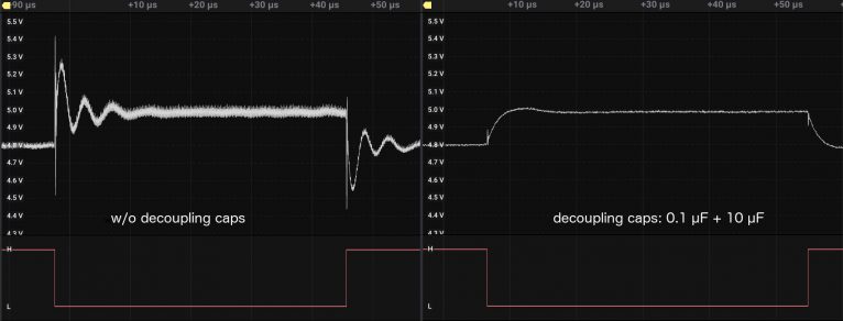
- Is there a 0.1 µF decoupling capacitor between the Vcc pin and GND pin of the MCU (with very short connections to the pin) and another global decoupling cap of 10 µF? Without it, the digital circuits in the MCU can lead to spikes on the power supply lines (see picture above), perhaps leading to erratic behavior of the MCU.
- Are the AVcc and AGND pins (the analog supply voltage pins) connected to Vcc and GND, respectively? They should be, even if you do not use the ADC (the analog to digital converter), since it powers also some digital pins. For best ADC performance, it also should have a separate decoupling capacitor.
- Is the AREF pin connected? If it is open, connect it to GND using a 100 nF cap. Otherwise, you might get back funny ADC readings.
Note that I have managed to make all three mistakes at some point, and it took quite a while to figure out what went wrong. There are other recommendations such as not leaving any MCU pin floating (i.e. unconnected and configured as input). I was never hit by a bug in this respect. In any case, it is possible to configure unconnected pins as outputs and this does not even waste any power. Therefore, one should always do it.
Switch bouncing
One of the misconceptions people coming from the software side have, is that a switch or button goes from an open state to a closed state (or the other way around) when it is switched. Unfortunately, this is true only to a certain degree, as the following picture shows.

When a switch is closed, it takes a while until the switch settles in the other state, and in between the switch may change its state a couple of times, it bounces. This is particularly annoying when one wants to count how often a button is pressed. So how long does a switch maximally bounce? In the example above, it is less than 10 µs. Jack Ganssle did a sort of empirical study and concluded that most of the switches bounce less than 10 ms, but there are outliers. So it is probably safe to assume switches bounce maximally 20 ms.
How do you deal with this problem? There is the hard way and there is the soft way. You can design some hardware to deal with this issue, where the cheapest way is to use an R-C circuit (or low-pass filter) as in the next picture.

If you choose 47 kΩ for R1 and R2 and 220 nF for C1, you get a response as in the following picture. In other words, only 12 msec after the button is pushed, the button is recognized as having been closed. This is not recognizable if the button is operated by a human. However, if it is a limit switch in a machine, this delay might be too much. If you are concerned that the signal is not a clean digital signal anymore: The AVR MCUs have Schmitt triggers at their inputs with a hysteresis of 50 mV, so the slowly decreasing voltage is not a problem.

Most people (in particular software people) prefer a software solution because you save a few cents, you save space on the printed circuit board (PCB), and you have this powerful MCU anyway. If you only deal with one button, then you might decide just to poll for the state of the button and start an action when the state changes, ignoring the button for the next 20 msec in order to filter out any bouncing. This probably works as long as you are in an environment that has no EMI (electromagnetic interference). When you want to protect against EMI or more than one button needs to be monitored, solutions will quickly become more complex. One solution could be to sample the state of the button inputs using a timer interrupt. More solutions and a more in-depth treatment of debouncing can be found everywhere on the web, and in particular in the blog post by Jack Ganssle.
To summarize, switch bouncing is a phenomenon you most probably have to deal with in an embedded system. You can solve the problem by hardware or by software, but you definitely cannot ignore it.
Pull-up resistors and I2C devices
When you want to do something useful with an MCU, you have to connect a sensor to the MCU. Interestingly, most of the sensors you can buy these days speak I2C, a 2-wire bus protocol developed by Philips. This protocol consists of the hardware layer (where the physical constraints are specified and how bytes are transferred) and the software layer (which tells you what kind of different states there are and how information between the parties is exchanged). For the Arduino framework, this is all encapsulated in the Wire library. Furthermore, for a huge number of sensors, there exist libraries that use the Wire library and deal with the particular sensor protocols. So the good news is that you can use these sensors in your programs without knowing anything about I2C or the particular sensor protocol. However, this also means that things can go wrong, and you do not know why.
On the hardware side, there are two common problems. First, you might have mixed up the SCL and SDA lines. The first thing when I2C is not working is that I exchange the connections. The second common issue is to have pull-up resistors that are too weak (with a value that is too high), or you have no pull-ups at all.
The two lines, SDA and SCL, are pulled up to Vcc by two pull-up resistors. They are either on your circuit board, or (often) on the sensor breakout board, or, if you use the Wire library, the MCU internal pull-ups (roughly 20-50 kΩ for AVR MCUs) are used. The recommended value for an I2C bus pull-up resistor is 4.7 kΩ. Resistors less than that are also OK. Since people want to save a few cents and space on the PCB, they typically rely on the MCU internal pull-ups. This may work most of the time, but probably not all the time. In order to demonstrate that, let us look at two extreme examples in the picture below.

To the left, you see the signals on the I2C bus with 100 kHz and pull-ups of 4.7 kΩ. The upper two rows show the analog voltage levels, and the lower two rows the digital interpretation. On the right side, you see the same with pull-ups of 220 kΩ. As you see, the electrical signals are so distorted that it is impossible to make sense out of it. So, the take-home message is: Have strong pull-ups on your I2C line. If this is not possible, then reduce the communication speed (so, here we have another instance of time-dependent bugs, which we have talked about in the first article). Below, you see the I2C communication with 220 kΩ pull-ups when the bus is clocked with 20 kHz.

Crosstalk
After you have developed your system on a breadboard, and everything works, you finally have designed a PCB and sent the design off to a fab. Now you have to wait … and when the PCB finally arrives, you eagerly build your system. Since it worked on the breadboard, it will work on the PCB as well, right? Wrong! There can be subtle differences that lead to problems. If different tracks run parallel for quite some length on the board, they open up the possibility of what is called crosstalk: if two wires next to each other carry different signals, the currents in them will create magnetic fields that will induce a smaller signal in the neighboring wire (Wikipedia). This is discussed in some detail in this article.
Recently, I suspected cross-talk on one of the PCBs I had designed. It turned out to be a case of parasitic power supply based on a programming error, though.
Electromagnetic interference
As already mentioned above, EMI or electromagnetic interference can make life very difficult. EMI can lead to wrong readings of your system inputs (or data paths). The above-mentioned crosstalk, e.g., is one form of EMI. I have never encountered any EMI problems so far, though. But if you want to operate your system in an environment where there is a lot of EMI, you should take precautions. The buzzword here is immunity-aware programming.
By the way, your little embedded system can be a source of EMI as well. A striking example of this is the FM transmitter built from just a single ATtiny45 MCU. As noted by the author, the emitted electromagnetic waves have a very low energy and so will not reach far. Selecting PB4 as an output for the system clock and connecting a cable to this pin might change this, though 😎.
Leave a Reply