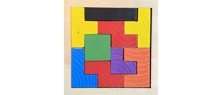
For a recent geocache, which is a tribute to the well-known Tetris game, I wanted people to solve a simple physical puzzle (as shown in the image above). As a reward, they get a code that they can use to open a box. So, what do you have to do to make things work? And how do you make sure that you do not have to change batteries for the next 20 years?
Constraining solutions
Before we address the question of how we can sense and detect possible solutions, we have to think about how many solutions there are. In the best case, there is a unique solution that we then can try to sense physically. However, this is clearly not the case for the unconstrained puzzle shown above. So, what about fixing one piece (e.g. the black one)? Does this lead to a unique solution?
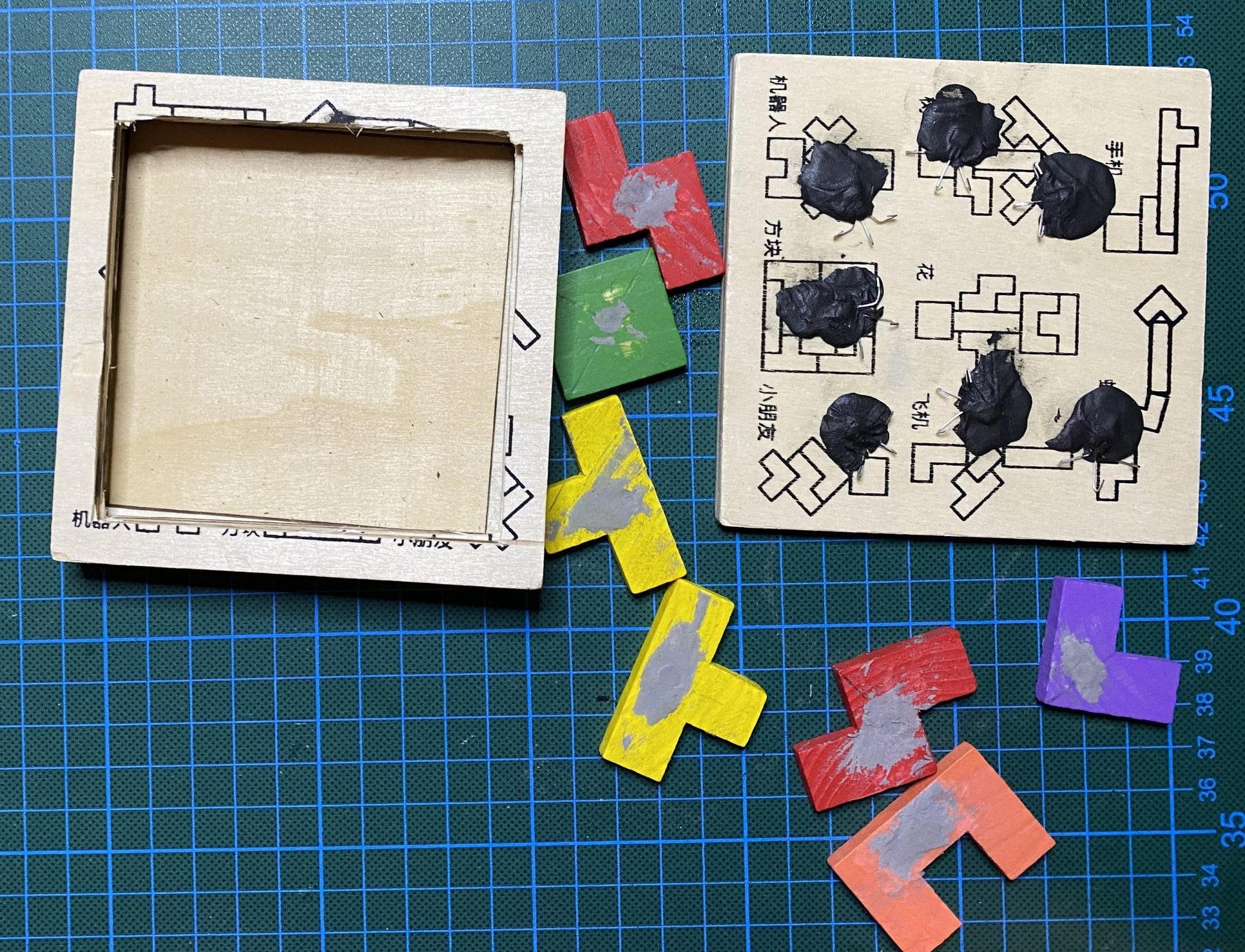
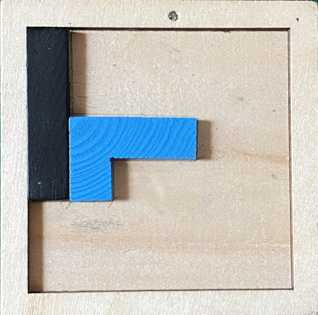 I wrote a little Python script that just searches through all the possibilities when one piece is fixed. In all these cases, the solution was not unique. Fixing two pieces, though, did the job. The combination shown in the left picture leads to a unique solution. Actually, this is only true if the red pieces are assumed to have one particular side up. In the picture, you also see the LED at the top of the puzzle board, which is used to blink the code that people need in order to open the box.
So, the only remaining problem is to come up with an idea of how to sense the presence of each piece (and do that in a way that is as power-efficient as possible).
Sensing pieces
Do we have to sense each type of piece individually, or is it enough to sense that all pieces are on the board? Well, the first alternative could be implemented using RFID. However, this would be awfully complicated and expensive. I am not even sure if there are solutions that work on this spatial scale. The second alternative seems OK if random configurations of pieces lying on the board have a very low probability of being taken as the solution. So, an idea could be that one tries to sense the presence of a piece at certain positions, where all the pieces have to lie flat on the bottom of the puzzle board. Since the wood itself cannot be sensed (with any sensor I know of) one has to put something into the puzzle pieces, e.g., a small magnet. These could be sensed using, e.g., reed switches or Hall sensors.
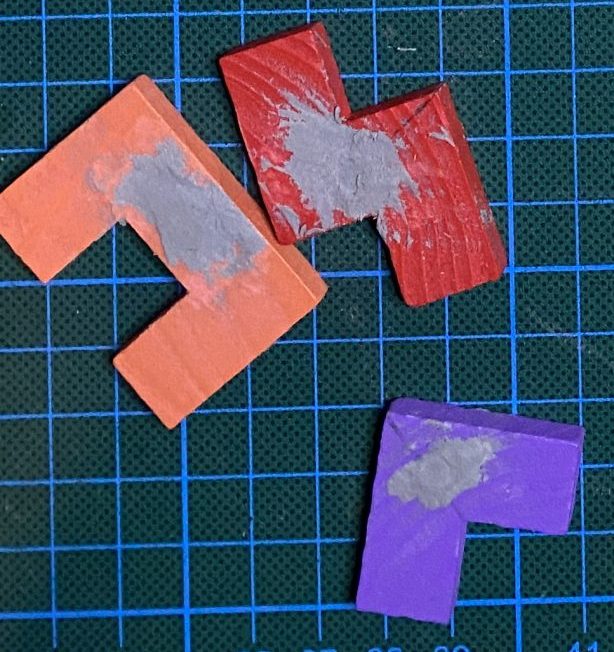 I put small Neodymium magnets into the puzzle pieces and used a bit of Sugru to affix them.
 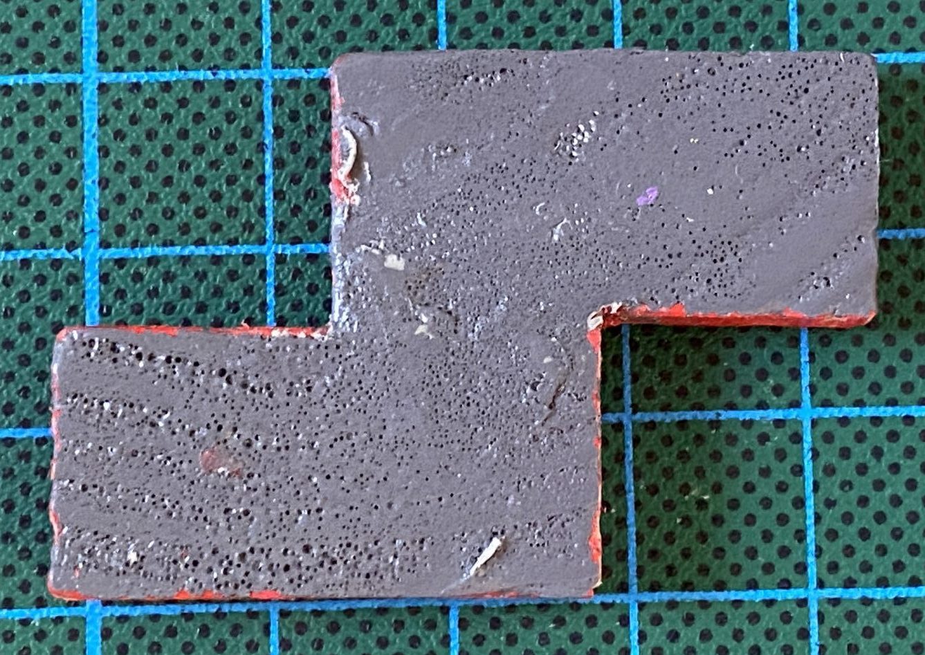 I then painted the bottom of the pieces gray so that people know which side of the pieces should be top and bottom. These magnets can then be sensed with Hall sensors, sensors that measure the magnetic field. Because the magnets cannot be very strong and because they cannot get arbitrarily close to the sensors, it is not possible to use digital Hall sensors that rely on strong changes in the magnetic field. So, I decided to use a relatively cheap analog hall sensor, the SS49E. You can operate the sensor with 2.7 to 5 V, it roughly needs a supply current of 5 mA and the sensitivity is around 1.0-3.2mv/Gs.
 I did some experiments, and it turned out that the magnets in the pieces could be sensed through the bottom of the puzzle board. So, I put all the pieces on the board, used magnets from the other side and marked the places, put the sensors at the marked places, and adhered them with Sugru (again). Now, we only have to connect the sensors to an MCU, write an Arduino sketch, and we are done.
Choosing (and modifying) a board
What kind of board should we use, or should we design our own? One of the main criteria is how many pins we need. One could interconnect all supply pins of the sensors and then source it from the common Vcc pin of the board. Then 7 analog to digital converter pins are required. If we source each sensor individually using a data output pin, we would need additionally 7 output pins. An Arduino Pro Mini would do the job in any case, and it also has the right form factor. Further, you can get it in a 3.3 V version running on 8 MHz, and it does not have a USB connector, so you require an additional USB-UART adapter for uploading programs to it. Why is all this an advantage? You save some money, some space, and you save energy (because no energy is wasted by a USB converter that we do not need).
When running a Pro Mini board with 5 V on 16 MHz, the board needs 21.85 mA according to an experiment run by Andreas Rohner. When we add the supply current required by the sensors, we are at 57 mA. Something that is not sustainable with a battery. But one can do better than that.
In the experiment mentioned above, Andreas also demonstrated that removing the power regulator and the power LED reduces power consumption significantly. Putting the MCU into a deep sleep state with the watchdog timer (WDT) switched off, he reduced power consumption to 20 µA. I was actually surprised by that because the datasheet of the ATmega328P states that the MCU draws only 100 nA when WDT is off. And when you have a look at the schematic of the Pro Mini board, there is no way that 20 µA is wasted somewhere. In fact, you get down to 100 nA as promised in the datasheet (provided you disable the brown-out detection).
If you are interested in modifying such a board and burning a new, modern bootloader to your Pro Mini, I have a detailed instructions in a tutorial on pimping your Pro Mini.
Low power design
So, 100 nA is the lower bound of what we can achieve when the MCU is in power-down mode. We will try to stay as much as possible in this range, even when the puzzle is somewhat active.
Wake-up sensor
We need something to wake up the MCU. My favorite sensor for that is a SQ-SEN-200 vibration sensor. It is a tad expensive when bought in Germany, but your favorite Chinese retailer may have them a bit cheaper (currently, they seem to be out of stock everywhere). These sensors are extremely sensitive. Picking up a board very, very carefully without shaking it will activate the sensor, which means a switch is opened. So, a pull-up resistor connected to one digital pin is required, and you have to use the pin change interrupt. The pull-up can have a pretty high value in this case. I use 5 MΩ. With a supply voltage of 3.6 volts, this means roughly 720 nA will be drawn by this pull-up, adding up to a total of 820 nA when the MCU is powered down. Is this enough to raise an interrupt? Strictly speaking, it is outside the spec, but it works beautifully. The spec says that the maximum input leakage current for each digital input pin is 1 µA, which then probably means that only 720nA could be drawn and the level at the input pin is 0V. But this is not what happens. The 1 µA leakage is extremely pessimistic. I measured a digital input with and without a 5 MΩ pull-up with my desktop multimeter Siglent SDM3045X a couple of thousand times and never got a reading with more than 10 nA. It might be the case that this input pin may cause trouble in an environment with much EMI. Further, it is probably not for high-frequency switching, but for detecting a change in the vibration sensor it is good enough.
Connecting the sensors
Powering all the seven Hall sensors at the same time will draw 35 mA. However, there is no need to power them all at the same time. It is even better. You can connect all their output lines and route them to one analog input pin of the MCU. When you then power up one of the sensors, you get just the reading from this activated sensor and there is no interference with the other sensors. So, you can save power and wiring at the same time!
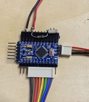 To the right, you see the connections of the board to the outer world. At the top, the black and red cable go to the battery. To the right at the top, you see the vibration sensor. In the middle is the pull-up. The right connector has two cables for the LED and one is the analog input. The bottom connector has a black cable as the common GND for all sensors, and the remaining cables go to the supply pins of the sensors.
Reading the sensors
When you want to get the inputs of all sensors, you can power each one up, read the sensor value, and then power it off again. This loop takes 440 µs and during this time the board draws 4 mA for the board and 5 mA for the sensor, i.e., 9 mA for 0.44 ms. The additional processing takes 100 µs i.e., 4 mA for 0.1 ms. In between two measurements, one can power down the MCU and use the watchdog timer to wake it up again. Actually, all the timing in the sketch is done by the watchdog timer and all waiting is done in power-down mode. All timers and all peripherals are switched off.
Now, how much time can you sleep before checking the state of the board again? I decided to make that dependent on how many pieces there are already on the board. In the beginning, 8 seconds are slept between two measurements. If only one piece is missing, we check every quarter of a second. This means that if the puzzle board is activated by being moved, it will most of the time sleep for 8 seconds and then make a measurement:
(8000 ms x 5.1 µA + 0.1 ms x 4000 µA + 0.44 ms x 9000 µA)/8000.54 ms = 5.64 µA
This goes up to roughly 18 µA when measuring every quarter of a second, which is still pretty low. If we take conservatively the average of these two values, it means that when the board is active, it draws not more than 12 µA on average. Compare that with the straightforward setup of powering the MCU in its unmodified version and powering all Hall sensors for all the time: 40 mA. This is a factor of 3000 and makes the difference between having a system run on one battery for 20 years or for 3 days.
Blinking the result
Once all the pieces are in place, a super-bright LED blinks the result. The LED draws 4 mA. It is on for 1/4 of a second for one pulse, with roughly 100 pulses per solution display (with repetitions of the result). So, overall this takes 100 mAs or 28 µAh.
Adding everything up
Let us now have a look at how much energy is consumed overall. Here we will distinguish between the energy consumed while sleeping and the energy necessary to solve the puzzle. The former is computed as the drain per year (assuming nothing happens). For the latter, we assume that the puzzle is solved in 60 minutes and then an additional 30 minutes are spent in waiting before going to deep sleep.
The self-discharge rate of Li-SOCl2 batteries is less than 1% per year. In our case, with a 2600 mAh battery, this means 26 mAh (or less). The MCU and the pull-up draw less than 1 µA, which is around 10 mAh per year, adding up to 36 mAh. Let us assume a lifetime of the cache of 20 years (very optimistically), which would require no more than 720 mAh. With a 2600 mAh Li-SOCl2 battery, which we conservatively assume to be able to use 2/3 of the capacity, we still have 1000 mAh for visits.
Assuming that solving the puzzle takes 1 hour (which is very much on the safe side), the visit will require the following charge (adding half an hour of “cool down” time and blinking the result):
12 µAh + 3 µAh + 28 µAh = 43 µAh
This means that we can cope with more than 20,000 visits during the next 20 years, implying that some mechanical, aging, environmental, or vandalism problems will most probably be the limiting factor for the lifetime of the cache.
Into the wild
Once all your ideas have been tried out and the Arduino sketch appears to work, it is time to build the final version, which hopefully is robust enough to survive a few years in the wild. Well, the users (geocachers) and the designer (I myself) are the problems here. Having worked in computer science for quite some years (but not in HMI), it is interesting to see that even a one-bit interface (a button) can sometimes be misinterpreted.
In the case of the puzzle, the human interface was not the problem (so far), but my decisions of what components to use. After I soldered everything together, I did the “final” test. However, two issues turned up. Sometimes, one piece was not recognized because there were a few millimeters of freedom in how the piece could be positioned on the puzzle board, and that made quite a difference in what the sensor readings gave us. Second, the sensor readings for all pieces seemed to vary randomly.
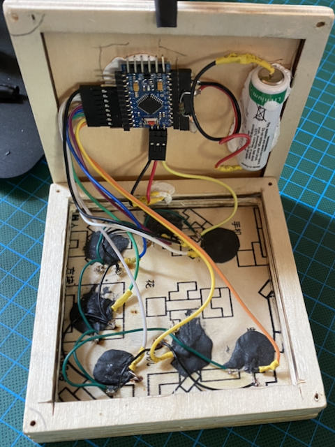
The first problem was mitigated by using magnets with 8 mm diameter instead of 5 mm. The second issue was caused by the white plugs seen in the picture above. They did not fit tightly and for this reason, led to different electrical resistance when moved slightly. It was not much, but dealing with an analog signal (the Hall sensor measurement) made this a critical point. I ordered DuPont plugs and after that, everything worked out. Below is a photo of the final working system before I closed the box. Note that I used Sugru again to glue the battery and the PCB to the box. The cool thing about Sugru is, it attaches reliably to almost everything, it lasts, and it is non-conductive.
In Action
And what does it look like when it is in action? It is not really spectacular. However, people who have used it like it. Here it comes …
Leave a Reply