
Featured image by Andreluiz Cunha from Pixabay.
Running on batteries does not carry your Arduino project very far? Well, when you want to run an Arduino project on batteries, you have to spend some thought on minimizing power consumption. Here we will look at what you can do when you use an AVR MCU. Often you will be able to reduce the average current consumption to a few microamps!
Motivation
In a battery-operated context, the MCU should usually run actively for only a limited amount of time. The rest of the time it should sleep and draw only minimal power (or none at all). Two typical use cases are:
- periodic sensor readings (say every 10 minutes) and then sending or logging them,
- short interactions, such as making a measurement and displaying the result after an activation by a user.
For the latter use case, one could also think of a power switch that disconnects the MCU physically from the battery. However, people often forget to switch off a device, and then the battery is quickly drained. Further, it is much nicer when the device switches on and off automatically when needed. As we will see, one can minimize power consumption to a point where it is significantly lower than the self-discharge current of a battery. This means this is almost as good as disconnecting the MCU from the battery.
Minimal hardware
The first recommendation for battery-powered Arduino projects is to refrain from using one of the standard Arduino boards as the target board for your project. Either design your own board, buy a minimal one such as the really bare bone board or the target board by Evil Mad Scientist,  or modify an existing one, e.g. a Pro Mini board. The reason is that we do not want to spend precious battery power on “power” LEDs, unused voltage regulators, or unused USB converters. The UNO board, e.g., uses roughly 50 mA. Depending on what frequency and supply voltage you use, you should be down to 3-18 mA when you use a bare-bone board.
By the way, it is a good idea to verify that you indeed have reduced the power consumption. For a rough estimate, a cheap multi-meter with 0.1 μA resolution is OK. A more accurate desktop multi-meter or the Current Ranger by LowPowerLabs is, of course, preferable. Make sure that you have disconnected everything else from your target system such as the ISP plug or FTDI plug before you measure. Otherwise, you may get a significantly wrong reading.
My experience with low-power projects is that one does everything written down in the specs and then there is still often one little thing one has ignored, resulting in a much higher power consumption than expected. That may be caused by the fact that the ADC has not been powered down or that you have left a pin in a high state that has an internal pull-down resistor, but only if the watchdog timer is disabled (I am not joking!).
LowPower library
The easiest way to save power is to use the LowPower library by rocketscream (as I have described it in one of my previous posts). You can install it via the Library Manager or download it from the GitHub repository.
The most important method is the powerDown method that sends the AVR MCU into the power-down sleep mode. In this mode, the MCU and all timers are stopped. The only ways to wake up the MCU are by an external interrupt, by a pin-change interrupt, by the watchdog timer interrupt, or by a TWI address match (when the MCU is configured as a TWI slave). There exist other sleep modes, which are also covered by the LowPower library. However, I had no use for them so far except for the idle mode (see below).
Try out the following call to the powerDown method:
LowPower.powerDown(SLEEP_FOREVER, ADC_OFF, BOD_OFF)
This call will send the MCU into the power-down state, disabling the ADC and the brownout detector. If you put this call into the setup or loop function, the MCU will stop execution and power down everything. When you measure the current consumption, it should be significantly lower than 1 µA.
Note that with a cheap multi-meter, you usually have an accuracy specified as something like 1%+3 counts meaning 1% error on the measured value and a maximum difference of 3 on the least significant digit. If the resolution is 0.1 μA, this means that a displayed value of 0.5 µA could in reality be anything between 0.2 µA and 0.8 µA!
Having the MCU powered down is great. But you want, of course, to wake it up again. As mentioned above, this can be done with an external interrupt (use Arduino’s attachInterrupt) or with a pin change interrupt, something that is not supported by the Arduino core. However, you can look up how to do it in the MCU spec or use a ready-made library.
If you want to wake up your MCU periodically, you have to specify something different for the first parameter. Possible arguments are SLEEP_8S, SLEEP_4S, SLEEP_2S, SLEEP_1S, SLEEP_500MS, SLEEP_250MS, SLEEP_120MS, SLEEP_60MS, SLEEP_30MS, SLEEP_15MS. Using one of these arguments when calling powerDown will enable the watchdog timer (WDT) to wake up the MCU after the specified amount of time.
How much energy do you need when sleeping?
The data sheets of common ATmega and ATtiny chips state that the power-down  supply current is between 0.1 µA and 0.2 µA when everything is switched off and the temperature is around 25 °C. However, is this also achieved in practice? And does it make a difference whether the pins are configured as inputs or outputs? How much energy is consumed by the BOD, the ADC and the WDT? In order to get an answer, I ran some experiments on an ATmega328P and on the ATtinys 84, 85, 1634, and 167. The following sketch specifies all the different settings I measured.
#include <LowPower.h>
#define MODE ALLOFF_INP
#define ALLOFF_INP 0
#define ALLOFF_OUTH 1
#define ALLOFF_OUTL 2
#define WDT_INP 3
#define WDT_OUTH 4
#define WDT_OUTL 5
#define BODON 6
#define ADCON 7
void setup() {
#if (MODE == ALLOFF_OUTH || MODE == ALLOFF_OUTL || \
MODE == WDT_OUTH || MODE == WDT_OUTL)
for (byte d=0; d < NUM_DIGITAL_PINS; d++) pinMode(d, OUTPUT);
#endif
#if (MODE == ALLOFF_OUTH || MODE == WDT_OUTH)
for (byte d=0; d < NUM_DIGITAL_PINS; d++) digitalWrite(d, HIGH);
#endif
}
void loop() {
#if (MODE == ALLOFF_INP) || (MODE == ALLOFF_OUTH) || (MODE == ALLOFF_OUTL)
LowPower.powerDown(SLEEP_FOREVER, ADC_OFF, BOD_OFF);
#elif (MODE == WDT_INP) || (MODE == WDT_OUTH) || (MODE == WDT_OUTL)
LowPower.powerDown(SLEEP_8S, ADC_OFF, BOD_OFF);
#elif (MODE == BODON)
LowPower.powerDown(SLEEP_FOREVER, ADC_OFF, BOD_ON);
#elif (MODE == ADCON)
LowPower.powerDown(SLEEP_FOREVER, ADC_ON, BOD_OFF);
#endif
}
Note that the ATtiny MCUs are not supported by the standard LowPower library. You have to download my own fork of this library if you want the LowPower library to work with ATtinys.
Below, you see the results of these experiments for the supply voltages of 3.3 V and 5 V. The MCU clock is irrelevant because all clocks are halted. I have to add that in order to disable BOD on the ATtiny85 and ATtiny1634, I had to program the corresponding fuse bits. I only have ATtiny85s with silicon revision B, which do not support BOD disable by software. And the ATtiny1634 does not support BOD software-disable in general, but you can disable BOD for the power-down state only using a particular fuse.
| Mode | Mega 328P 3.3 V | Mega 328P 5.0 V | Tiny 84 3.3 V | Tiny 84 5.0 V | Tiny 85 3.3 V | Tiny 85 5.0 V | Tiny 1634 3.3 V | Tiny 1634 5.0 V | Tiny 167 3.3 V | Tiny 167 5.0 V |
|---|---|---|---|---|---|---|---|---|---|---|
| All off, pins input | 0.11 | 0.14 | 0.09 | 0.12 | 0.18 | 0.46 | 0.09 | 0.10 | 0.09 | 0.11 |
| All off, pins output high | 0.11 | 0.14 | 0.09 | 0.12 | 0.18 | 0.46 | 416 | 711 | 0.10 | 0.11 |
| All off, pins output low | 0.11 | 0.14 | 0.09 | 0.12 | 0.18 | 0.46 | 0.09 | 0.11 | 0.10 | 0.11 |
| WDT on, pins input | 4.18 | 6.14 | 4.51 | 6.26 | 4.81 | 7.03 | 2.09 | 4.06 | 4.47 | 6.35 |
| WDT on, pins output high | 4.18 | 6.14 | 4.51 | 6.26 | 4.81 | 7.03 | 2.09 | 4.06 | 4.48 | 6.35 |
| WDT on, pins output low | 4.18 | 6.14 | 4.51 | 6.26 | 4.81 | 7.03 | 2.08 | 4.07 | 4.47 | 6.35 |
| BOD on | 18.1 | 20.4 | 16.9 | 19.0 | 18.5 | 21.1 | 18.3 | 20.6 | 18.2 | 20.6 |
| ADC on | 106 | 135 | 221 | 299 | 246 | 327 | 225 | 300 | 238 | 317 |
The results appear to be in alignment with what the data sheets state. There is one surprise in the ATtiny1364 columns, though. 416 µA (3.3 V) or 711 µA (5V) in the power-down state appears to be excessive and happens only when the pins are high outputs and when the WDT is not running. The explanation for this strange behavior can be found in the errata section of the datasheet:
Port Pin Should Not Be Used As Input When ULP Oscillator Is Disabled
Datasheet Attiny1634 Errata section
Port pin PB3 is not guaranteed to perform as a reliable input when the Ultra Low Power (ULP) oscillator is not running. In addition, the pin is pulled down internally when ULP oscillator is disabled.
Problem Fix / Workaround
The ULP oscillator is automatically activated when required. To use PB3 as an input, activate the watchdog timer. The watchdog timer automatically enables the ULP oscillator.
Honestly, how long does it take for you to connect this statement with the table entries above? It took me the better part of an evening to make the connection. First, you have to understand that there is also a problem if you have PB3 configured as an output (because then the pull-down draws current). Second, you have to ignore the “problem fix” and set the pin to the low state (or make it an input) while sleeping.
Apart from that, however, the 1634 does pretty well when the WDT is running. It is only 2 µA (at 3.3 V) compared to 4-5 µA (at 3.3 V) for all the other MCUs! In addition, it has 16 kByte flash memory, 1 kByte SRAM, 17 usable GPIOs, 2 USARTs (!), ADC, and all the rest. For this reason, it is meanwhile my favorite ATtiny. The only problem is that you have to learn to solder SMD parts.
When comparing the table entries with the measurement results Nick Gammon came up with in his very readable low-power tutorial, one notices that in Nick’s case, the power-down supply current for the “all off” mode is 0.35 µA when the pins are configured as inputs and 1.85 µA when the pins are configured as outputs and are in high state. It turns out that Nick appears to have forgotten to connect AVcc and AGND to Vcc and GND, respectively (see the photo of the Evil Scientist board in his post). Indeed, when I disconnect these pins, I measure the same values as Nick did. Let me re-iterate rule 2 from one of my previous posts: Always check whether AVcc and AGND are connected!
Periodic wakeups
If you want to wake up the MCU periodically, say every 10 minutes, you have to count the number of 8-second-wakeups, i.e., you have to count to 600/8=75. The interesting question is how much extra power this counting needs. In order to get an idea what the resulting average supply current is, one takes the average of the power-down supply current I_{sleep} and the active supply current I_{active} weighted by the time sleeping t_{sleep} and the time being active t_{active} :
I_{avg} =\frac{t_{sleep} \times I_{sleep} + t_{active} \times I_{active}}{t_{sleep} + t_{active}}
The active time consists of the wake-up time and the computation time. The wake-up time depends on what kind of clock source you use. The data sheet states that the internal oscillator needs 6 clock cycles, a ceramic resonator needs 1000 cycles, and a crystal oscillator needs 16000 cycles before it is stable. So, you have to adjust the fuse bits accordingly in order to avoid running with an unstable oscillator. If one has disabled BOD by software, then the minimum wakeup time is 60 µs, as stated by the datasheet: When the BOD has been disabled, the wake-up time from sleep mode will be approximately 60 μs to ensure that the BOD is working correctly before the MCU continues executing code.
Incrementing an integer variable, comparing it with a constant and going to sleep again is doable using roughly 100 instructions, i.e., less than 300 cycles. Assuming a 16 MHz clock, we would sleep for 8,000,000 µs and be active for (300+x)/16 µs, where x is the number of wakeup cycles. Assuming a 6 µA sleep current, 16 mA active supply current, and 16k cycles to wake up, we end up with an average supply current of
\frac{8000000 \mu{}s \times 6 \mu{}A + 1019 \mu{}s \times 16000 \mu{}A}{8001019 \mu{}s} = 8.03 µA.In other words, the additional counting costs roughly 2 µA on average. With the much shorter wake-up time of a resonator, it would only be 6.16 µA, and with the internal oscillator only be 6.03 µA.
If you want to save even more power and/or you have the requirement to wake up at precisely specified times, then you could think of adding a real-time clock that triggers the wakeup of the MCU. With such a regime you can be down to less than 1 µA supply current while sleeping. There are RTCs such as DS3231 that have an accuracy of 2ppm, which implies a timing error of one minute per year. Actually, it is possible to calibrate the clock in order to minimize the timing error resulting in much higher accuracy, as reported by Pete. With such a setup, you can run an autonomous sensor node for years on one battery with a minimal timing error of a few seconds per year.
Saving power while awake
So far, we only talked about sleeping. However, you probably also want to save power while awake. There are basically five ways to do so:
- Changing the clock source
- Reducing the clock frequency
- Reducing the supply voltage
- Disabling unused MCU modules
- Use power-saving modes
Changing the clock source
Before we go into the details, let us first establish a baseline. This baseline is a bare-bone ATmega328P running at 5 volts on 16 MHz using a crystal oscillator, either on a special target board or a pimped Pro Mini. In the ATmega328P datasheet, you find the following figure:
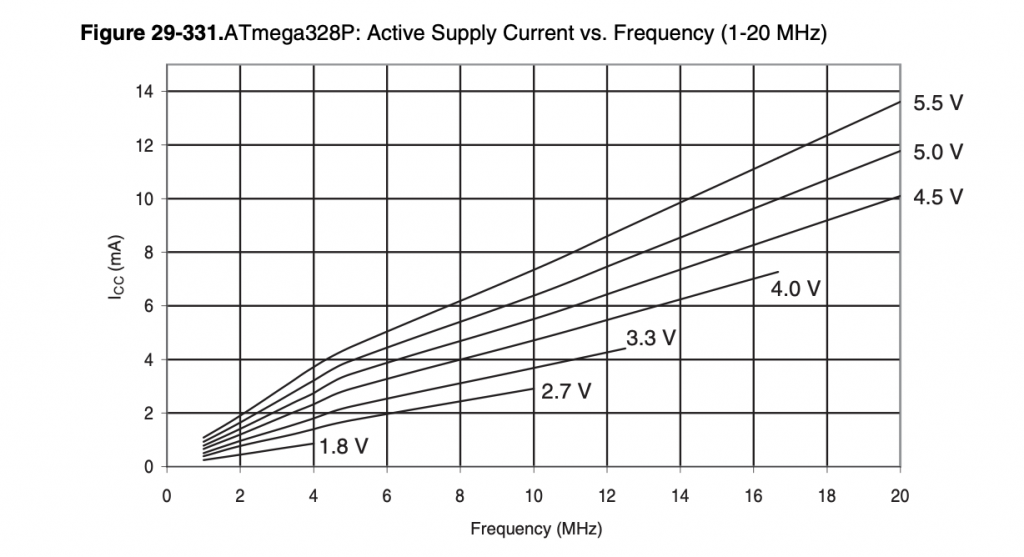
From it, you might be tempted to conclude that our baseline MCU would consume around 9.5 mA. Using a sketch with empty setup and loop functions, I measured between 15.0 and 18.5 mA for different chips. Others measured up to 24 mA. It is not clear to me what the cause for this kind of variability is.
Let us consider one particular exemplar that used 16.9 mA in the standard configuration. You can change the supply current by changing the clock fuse bits and the oscillator. By switching the clock fuse from a low power crystal oscillator to a full swing oscillator, you can enhance robustness, but you also will increase current consumption by roughly 1 mA. On the other hand, if you exchange the crystal for a ceramic resonator, you will lose accuracy in timing (going from 30ppm to 1%), but you can also save power in the range of 1 mA, and wakeup time is reduced (see above). Similarly, you save some power when moving from a crystal oscillator to the internal oscillator. Note that the internal oscillator is factory-calibrated up to an accuracy of 10%. This can be enhanced by user calibration to 1% using, e.g., my calibration sketch.
Reducing the clock frequency
Much higher savings are, of course, possible when reducing the clock frequency as should be evident from the figure above. However, by reducing the clock frequency, one needs more time to compute something. So, in particular, in applications where the MCU is only awake for a short amount of time in order to read a sensor, it may not make much sense to reduce speed. However, when the MCU is awake for a longer time and a lot of that time is spent busy waiting, then reducing speed is an option. Again, for 5 volts the above figure gives optimistic values, which one does not seem to achieve in practice.
Reducing the supply voltage
The interesting point when having reduced the clock frequency is that you also can reduce the supply voltage. With 8 MHz, 3.3 volts is enough. This is good news because one often wants to interface to 3.3-volt sensors. Further, reducing the supply voltage reduces the supply current. For 8 MHz at 3.3 volts, the supply current should be 3 mA according to the figure above. And one indeed gets numbers around 3.5 mA. Compared with our baseline, this is a reduction by more than a factor of 4!
As a matter of fact, I run most of my fielded projects this way. One of the main reasons is that I can then use Li-SOCl2 batteries, which have a nominal voltage of 3.6 volts. Another reason is that I do not need an external crystal oscillator. And finally, 8 MHz was enough for almost all my projects so far.
Disabling unused modules
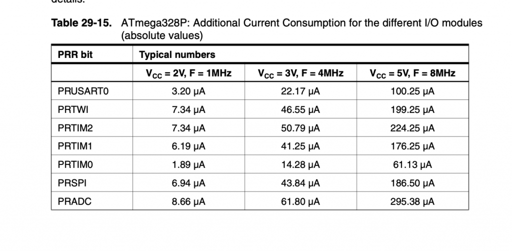
AVR MCUs contain a number of useful modules such as ADCs, UARTs, SPI and TWI interfaces, and timers. Most probably, you are not using all of them. In this case, you can switch the unused devices off. You can either directly modify the power reduction register PRR or you have to include avr/power.h and then you can use macros to disable each peripheral (or all of them). For the ATmega328P, there are the following macros:
power_usart0_disable()power_twi_disable()power_timer2_disable()power_tiner1_disable()power_timer0_disable()power_spi_disable()power_adc_disable()power_all_disable()
Note that before disabling the ADC, one should stop the ADC by setting ADCSRA to 0.
There exist also macros to reenable each device (with _enable). However, one must note that some devices have to be initialized again. So, I would only disable devices that are never used.
In order to get an idea, how much power can be saved, consider the following table, which shows that the savings are not mind-boggeling.
Use power-saving modes
Even when awake, it may be possible to take a quick nap. When looking at the different power-saving modes of the AVR MCUs, there is in particular the idle mode that looks promising. All devices and timers will continue to run, only the CPU clock and the flash memory clock is halted. This means that all external and internal interrupt sources will be served immediately. In particular, millis() counting will not be affected. On the other hand, the millis interrupt will terminate any idle call after at most one millisecond (or two milliseconds when running on 8 MHz).
I used the idle mode in my own delay function, which looks as follows:
void idledelay(unsigned long msecs)
{
  unsigned long start = millis();

  while (millis() - start < msecs)
    LowPower.idle(SLEEP_FOREVER);
}
When using this idle delay function in the loop function as the only action on an ATmega328P with 3.3 V and 8 MHz clock, then one reduces current consumption significantly. Assuming an active supply current of 3.5 mA, an idle supply current of 1 mA, and an active time of roughly 200 instructions for serving the millis interrupt, i.e., less than 600 cycles, we arrive at 1.09 mA average supply current. So, this is actually a clear winner, in particular for cases where one uses a lot of delay calls.
What about the other power-saving modes? Well, they all stop Timer0 and for this reason confuse Arduino’s timekeeping. I actually found never a good use case for them.
Switching off external devices
Our focus so far was on the power consumption of the MCU. However, there are usually sensors, displays, LEDs, servo motors, and other peripherals that are controlled by the MCU. And they consume energy even they are not used, often much more than the MCU in active mode.
As with the MCU, the obvious way to save power is to power down external devices as often and as long as possible. So, e.g., if you need an “alive” indicator, instead of having an LED permanently on, it is enough to blink it every 30 seconds for 200 ms. As another example, in one of my projects, I have an RFID receiver that needs around 20 mA. Instead of having it on all the time, I switch it on only when the device is held upright, because only in this position it is supposed to read an RFID tag. Of course, one needs an additional sensor to sense the orientation. However, a sensor such as the BMA250 needs only 16 µA in low-power mode, provided one gets rid of the power regulator on the breakout board.
An Atmega328P, an ATtiny84, or an ATtiny85 can sink or source up to 20 mA per output pin, for an ATtiny1634 it is only 10 mA. Note, however, that the more current is drawn, the lower the output voltage. For example, when sourcing 10 mA through an output pin on an ATtiny1634 at Vcc=3 V, the output voltage is only 2.5 V. I usually switch anything with a supply current of 5-10 mA directly through an output pin, which up to now worked perfectly. If you want to have really bright LEDs or 7-segment displays, you have to use the super bright types that are usually a bit more expensive, but they are still visible even with supply currents of only 3-4 mA. Note that there is also an upper limit to the total current flowing through the Vcc and GND pin, which is 200 mA. So far, I never came even close to this limit.
If you want to switch a device that needs more than 10 mA, you need to use an electronic switch. There are two kinds of such switches, high-side and low-side switches. The former kind of switches is located between the load and the supply voltage (on the high-side of the load), and the latter kind is located between the load and ground. The Baldengineer has a very nice tutorial on that.
Instead of using transistors (BJT or MOSFET), there are also so-called load switches that contain MOSFETs and some more stuff to switch power for devices. They usually have also overload protection and reduce the rise time so that current peaks are avoided. One example is the TPS2041, which can switch up to 500 mA with a maximum of 5.5 V. There are other such switches, which can switch even higher voltages, but interestingly most of them appear to be sold out these days (in 2021).
Battery lifetime
Since this post is on how to run an Arduino project on batteries, we have to talk about the different kinds of batteries that are out there. The important parameters are nominal voltage, capacity, and self-discharge rate. I have collected a few typical values from the web for the survey table below. Capacity values are for typical exemplars and the capacity in real life depends, of course, on a number of things such as temperature, discharge current, usage pattern, and probably more. The self-discharge rate is a crude approximation based on numbers I found on the web. However, they should give you a good idea of what to expect from a battery. And they can be used as an approximation to compute the equivalent average self-discharge current (an idea I got from Nick’s tutorial mentioned above). Assuming conservatively that each month the same amount of battery capacity given by the percentage of the fully charged battery is discharged, one can easily compute the capacity discharged in one hour by dividing the amount by 24\times 30. If x mAh are discharged in one hour, this means there is a current flowing of x mA for one hour, i.e., x is the equivalent average self-discharge current.
| Type | Nominal voltage | Capacity mAh | Self-discharge rate per month | Equivalent self-discharge current in µA | Rechargable |
|---|---|---|---|---|---|
| AAA LSD-NiMH | 1.2 | 800 | 2% | 22 | Y |
| AAA NiMH | 1.2 | 1000 | 25% | 347 | Y |
| AA LSD-NiMH | 1.2 | 1900 | 2% | 53 | Y |
| AA NiMH | 1.2 | 2500 | 25% | 868 | Y |
| AAA Alkaline | 1.5 | 1000 | 0.5% | 7 | N |
| AAA LI-FeS2 | 1.5 | 1200 | 0.1% | 1.6 | N |
| AA Alkaline | 1.5 | 3000 | 0.5% | 21 | N |
| AA Li-FeS2 | 1.5 | 3000 | 0.1% | 4.1 | N |
| CR2032 Li-MnO2 | 3.0 | 230 | 0.1% | 0.3 | N |
| AA Li-SOCI2 | 3.6 | 2600 | 0.1% | 3.6 | N |
| 9V battery NiMH | 8.4 | 200 | 25% | 69 | Y |
| 9V battery Alkaline | 9.0 | 500 | 0.5% | 3.5 | N |
| 9V battery Li-FeS2 | 9.0 | 1000 | 0.1% | 1.4 | N |
With these numbers, you can now estimate the battery lifetime for a sensor node or an interactive gadget. For a sensor node, you compute the average supply current (as we did in the section on periodic wakeups) this time adding the self-discharge current. You can then divide the capacity by the average supply current and the result is the battery lifetime.
Assume you have a sensor node that wakes up every 30 minutes, makes a measurement, and then sends the measurement using an RF module, e.g. the RFM12B. Sending a telegram needs 10 ms drawing 25 mA, waiting for an ACK may take another 10 ms at 15 mA. On top of that, we have the 3 mA for running the MCU. Let us approximate that to 30 mA for 20 ms (which already should include the wakeup time). Let us assume a power-down current supply of 5 µA and a Li-SOCI2 battery with a self-discharge current of 3.6 µA, which adds up to 8.6. µA. Then the average supply current is:
\frac{8.6 \mu{}A \times 1799980 ms + 30000 \mu A \times 20 ms}{1800000 ms} = 8.9 \mu{}A.This means, our battery should last for 2600000 \mu{}Ah/8.9 \mu{}A = 292134 h = 12172 d = 33 y. In other words, we can deploy this sensor node and then forget about it! If this is too much manual computation, you can instead use the battery life calculator. Note that this calculator gives 27 years instead of 33 years as a result. The reason is that this calculator uses a derated battery capacity of 85% of the nominal capacity, but it ignores self-discharge. One can now make some calculations easily and notice that waking up the sensor every 10 minutes decreases the battery lifetime by only 10% to 30 years. Using cheaper batteries such as Alkaline AA batteries (here we would need two) gives us 10 years. However, I am not sure whether Alkaline batteries really last 10 years.
Estimating battery lifetime for an interactive gadget is much more difficult because it is hard to predict the usage pattern. As an example, let us assume a luggage scale that uses a CR2032 battery. Here we can probably assume a power-down supply current of 0.5 µA (or less). The self-discharge is 0.3 µA adding up to 0.8 µA. In active mode, the MCU might draw 3 mA, the display probably another 4 mA, and the scale sensor (a HX711) 1.5 mA, altogether 8.5 mA. You usually use it for 30 seconds. Depending on how much you travel, you probably use the scale less than 120 times per year. So, each year we consume 8 mAh for power-down and self-discharge current and 8.5 mAh for active usage, i.e., altogether 16.5 mAh per year. This means that the battery can live up to 14 years. Not all such luggage scales are designed this way, unfortunately. I own a cheap Chinese luggage scale where the battery is drained in about half a year while not using the scale at all. So, I always have to remove the battery after using it in order to save power.
The term battery capacity has so far been used in a way suggesting that after having used up the capacity the battery is dead. However, there is no such point when the battery is completely empty. In fact, the capacity is usually specified with the qualification of a cut-off voltage. For example, for Alkaline batteries this threshold is usually specified as 0.9 volts. NiCd and NiMH batteries are usually only used down to 1.0 volts in order to avoid damage to the cells. For LI-SOCI2 batteries, the company SAFT specifies that the nominal capacity is with respect to a cut-off at 2.0 V. Because of the the requirements of external devices such as displays or sensors and because of the clock speed of 8 MHz, the supply voltage should not be below 2.5 V, though, which implies that one cannot use the full capacity of the battery. Fortunately, however, the discharge curve of the LI-SOCI2 batteries is very flat so it does not make a big difference whether we cut off at 2.5 or 2.0 volts (see below) with this kind of battery.

Voltage regulators
Above, we assumed that the battery is directly connected to the MCU and perhaps to external devices. Indeed, this is the preferred setting because no energy is wasted. However, sometimes it may be necessary to use voltage regulators. One scenario is when you need sometimes more than just a few milliamps, say 60 mA. Then the above-mentioned Li-SOCI2 has a problem. The voltage will go down to 3.1 or even to 2.6 V (if it is very cold).
If I need a battery that also can deliver higher currents, I rather power my project with 4 AA(A) batteries or a 9-volt battery and use a linear regulator that transforms the unused volts into heat. The standard regulator for doing so is the LM7805. However, this is not a regulator you want to use in a battery-powered device. First, it has a dropout voltage of 2 V, i.e., it needs at least 2 volts more than is delivered at the output. Second, it has a quiescent current of 8 mA, i.e., it burns 8 mA even if there is no load.
Instead, you want to use low dropout (LDO) regulators with a minimal quiescent current. Examples of that are MCP 1702 and HT75XX-1. They have both a very low dropout voltage and a quiescent current of around 2 µA, something that we accept in a low-power design. While the MCP1702 has a higher potential output current (250 mA), the HT75XX-1 (100 mA) has the advantage that it also works reasonably when the input voltage is below the nominal output voltage. The MCP1702 drains the battery when it comes close to the nominal output voltage, while the HT75XX-1 passes through the current without going crazy.
Instead of using linear regulators, one can think of switching regulators that transform low voltage to higher voltage, so-called boost converters. I have not used any of those in my projects yet since they usually have quite a high quiescent current of more than 0.5 mA, e.g., the U1V10F3 by Pololu. This is OK when you have a high self-discharge current anyway, but looks like a waste of energy when you, e.g., use Alkaline cells.
The MCP 1640 booster IC looks very promising when studying the data sheet. It has a quiescent current of less than 20 µA, can deliver up to 100 mA, and starts to work around 0.8 V. At 0.8 V input voltage it still is supposed to have an efficiency of 80% when the output current is 10 mA. However, the breakout boards I have do not deliver. The board that should deliver 100 mA at 3.3 V went into overdrive when the load was only 10 mA and the input voltage was 1.2 volts. It then had an input current of 120 mA!
LTC3525 is another booster IC that fits into the low-power category. It has a quiescent current of 7 to 30 µA depending on the input voltage and can deliver at a fixed voltage of 3, 3.3, or 5V up to 60-150 mA output current. It has an efficiency of more than 90% for an average load. Jeelabs sells the so-called AA board with one of those. I’ll definitely give it a try!
There are also switching regulators that have a lower output voltage than input voltage, so-called buck converters, and there are regulators that go both ways. I never have seen one that has a low quiescent current though. I plan to use one of those for a project, but it will have to be shut down, i.e., disconnected from the battery during the sleep periods.
Monitoring the supply voltage
As mentioned above, the supply voltage decreases over time when you run on batteries. This means you have to decide at some point to switch the system off or not to start it anymore. If you operate an AVR MCU on a voltage level that is below the specified threshold, you may corrupt the EEPROM memory and the flash memory. Further, if you use a display, this will stop working at some point.
You may think that this would be an ideal use case for the brownout detection system. However, most of the time you need to stop using the system before you have reached a voltage level critical for the MCU. So, I usually disable the BOD completely in order to save energy and wake-up time and monitor the supply voltage when waking up once. One can use the ADC for this purpose using the supply voltage as the reference voltage and measure the internally generated bandgap voltage of 1.1 V. Actually, depending on the exemplar (the temperature and the supply voltage), the real value is something between 1.0 and 1.2 V.
In order to eliminate the variability concerning the exemplar, I wrote a calibration sketch that you can use, even if there is only access to the ISP pins. This sketch writes the calibration value into the EEPROM if you desire. The Vcc library can then be used to make quite accurate measurements of the supply voltage. Based on that the MCU can give a low voltage warning if the battery voltage is too low.
One would think that this method does not work when you use a voltage regulator, because in this case, you would measure the regulated voltage. Well, for the linear regulators it works when they work in pass-through mode once the voltage is below the input threshold. For switching regulators, it really does not work. However, Jean-Claude Wippler from Jeelabs has a solution for that.
Summary
In summary, running an Arduino on batteries is not complicated:
- avoid unnecessary hardware such as power LEDs, unused USB converters, or unused voltage regulators,
- sleep as much as possible (and switch off ADC and BOD beforehand),
- run on 8 Mhz with 3.3 volts (or less),
- use your own delay function that employs the idle sleep mode,
- switch off external devices as often as possible,
- avoid voltage regulators if possible,
- if you have to use voltage regulators use ones with low quiescent current, and
- monitor the battery voltage.
The most important point in low-power projects is, I believe, to test your system for the low-power property before you deploy it. As I mentioned at the beginning of this tutorial, there are often very subtle things that can lead to much higher supply currents than expected. And these issues are only discovered when you test your system under realistic conditions.
Leave a Reply