dw-link can turn your Arduino board into a hardware debugger, and dw-probe connects it to any target board.
How to connect the hardware debugger to a target
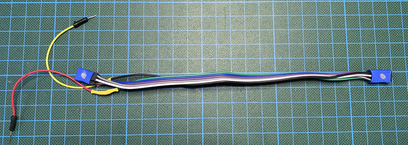
As I reported in a recent blog post, the dw-link sketch can turn your Arduino Uno, Nano, or Pro Mini into a hardware debugger. However, the hardware part is very limited and leaves a lot to be desired. You have to use 6 jumper cables to connect the “hardware debugger” to the target. If you want to use this tool more than once, then one wants to have at least something like an ISP cable connection. I built something along this line using a 6-wire Dupont jumper cable and heat shrink tubing.

While it is better than just 6 flying wires, you still have to remember which wire has to be connected to which Arduino pin. A little more convenient would be an ISP-cable with broken out RESET- and Vcc-wire.
A prototype shield with an ISP connector is definitely an improvement over the above solutions. It can also have a jumper that connects the supply pin with the hardware debugger supply pin (for power-cycling) and perhaps the system LED, as in the next picture. The connections are straight-forward. If you are curious, you can find a Fritzing sketch in the dw-link manual.

While this shield was enough for developing the dw-link sketch, it is limited when it comes to using it in real applications. I for my part usually work with 3.3 V systems and use in particular sensors that are not 5 V tolerant. So, what one needs here are level shifters. And they should be adaptive to the target system so that you can debug both 3.3 V and 5 V systems. This is easily achievable by using, e.g., the Sparkfun level-shifter breakout board with four BSS138 N-channel MOSFETs. Of course, similar breakout boards work as well.
I built a prototype, this time using a breadboard shield, and it worked beautifully. Again, you can find a Fritzing sketch in the manual, if you are interested to build it.

Maybe it does not look completely convincing, but it does what it is supposed to do. In particular, the level-shifting works flawlessly. However, it is definitely not made for eternity. And even when I would give it a more sustainable form, this prototype has a few shortcomings. First, it has pull-up resistors at the outgoing SPI lines, i.e., it changes the electrical properties of these lines considerably. Second, when powering it with 3.3 volt from the Arduino board, one should source not more than 50 mA. Third, the board cannot power-cycle the target board when interfacing to a 3.3V board.
The greatest thing since sliced bread: dw-probe
So, it would be great to have a board with the following features:
- Switchable target power supply (supporting power-cycling by the hardware debugger),
- offering 5 V and 3.3 V supply at 200 mA,
- a bidirectional level-shifter on the debugWIRE line,
- an optional pull-up resistor of 10 kΩ on this line,
- unidirectional level-shifters on the ISP lines, and
- tri-state buffers for the two output signals MOSI and SCK.
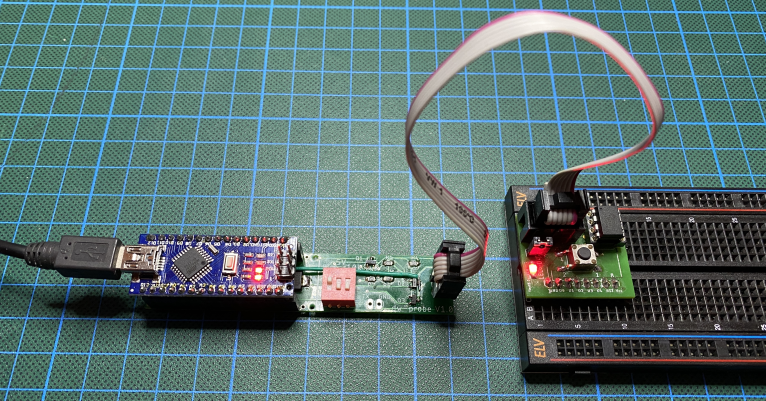
I designed a board for a Nano or Pro Mini Arduino to be plugged in, which has all the above features. And as usual, I forgot one connection to draw. This is the green wire you see in the picture. Version 2 of the board will not have this flaw (and will correct another bug). Furthermore, it will be smaller. In any case, the current version works flawlessly after the two corrections.
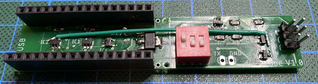
If you plan to build the board by yourself, I have to warn you that the SOT23-5 ICs are not much fun to solder. However, it is doable if you have a good magnifying glass. The Eagle design files can be found in the pcb directory of the repository. As long as I have spare boards, I will also mail boards for the price of the production and postage.
EDIT (05-Oct-2023): You can now buy an Arduino UNO shield (as a PCB, a kit or assembled) at Tindie. It is a bit simpler and easier to build.
Leave a Reply