
The featured image of this blog post is by Chen from Pixabay
What is a real-time clock? Why do you need one? What are the use cases? How accurate can a real-time clock be? Which features can a real-time clock have? Which models are around? And which one should you buy?
What is a real-time clock?
A real-time clock (RTC) is an electronic device that keeps track of the time of day. But isn’t that what computing devices do anyway? Not necessarily! Computing devices usually maintain an internal time, which measures the time units since the system has been started. This is enough for most purposes, e.g., measuring time intervals and enforcing the order of certain events. An Arduino system, for example, usually counts the number of milliseconds (and microseconds) since it was started. Only when the time of day becomes part of the interaction with the outside world, e.g., when a box should only be opened at a particular time of day, then a real-time clock is needed.
Why do you need an RTC?
While it might seem reasonable to synchronize the internal time of a computing system with the time of day (e.g., at startup), there are many good reasons not to do so. One reason is that when an MCU is in power-down mode, (internal) time does not advance, but the time of day does. Another reason is that one often wants to adjust the time of day, e.g., because of a misalignment or changes because of daylight saving time. In these cases, the time of day changes non-monotonically, while internal time is expected to change always strictly monotonically. For these reasons, the Unix standard POSIX distinguishes between a time-of-day clock, called CLOCK_REALTIME, with a fixed start time of 1st of January 1970, and a monotonically increasing clock, called CLOCK_MONOTONIC, with an undefined start time.
Having said all that, you can still synchronize internal time with the time of day (and call that software RTC). You should just be aware of the problems spelled out above. In particular, you have to set the time of day each time the system is started or woken up after being suspended in power-down mode.
Use cases
An RTC can be used for everything where the time of day is needed. This is, for instance,
- displaying the time of day on a clock,
- synchronization of events between different systems,
- time-based access control,
- the generation of time-based one-time passwords (TOTP),
- logging of measurements at given time points, and
- periodically waking up a system at precisely defined time points.
While almost all the use cases mentioned above could be implemented using a software RTC, the last one cannot, precisely because an MCU does not keep the time when in power-down mode. All the AVR MCUs can periodically wake up every 8 seconds (nominally). However, the internal WDT timer is so inaccurate that one wouldn’t call that time-keeping (the nominal 128 kHz oscillator runs at 115 kHz at room temperature), and sleeping with the watchdog timer enabled draws around 5 µA. Using a decent RTC and putting the MCU into the power-down mode with the watchdog timer disabled and waking the MCU using an RTC interrupt could lead to a tenfold reduction, i.e., to less than 0.5 µA. More powerful MCUs such as the ESP8266 or RP2040 have already a built-in RTC, which can be used to wake up the MCU. However, even in those cases a separate RTC can make sense, be it for accuracy reasons or because the external RTC has a battery backup.
Finally, let me point out that real-time computing (also abbreviated RTC) is not a use case for real-time clocks. In real-time computing, one has to guarantee that system responses to external events are always on time. So in this case, internal time is important, but the time of day does not play any role.
Accuracy
Depending on your requirements, the accuracy of an RTC can be a more or less important feature. If the computing device is connected to the internet or can use a DCF77 or GPS receiver, it can easily re-adjust the time of day. However, if you plan to deploy a sensor node somewhere in the wilderness, you would like to have an RTC that is as accurate as possible. So, what accuracy can one expect?
The accuracy of clocks is measured by part-per-million (ppm) or part-per-billion (ppb). An accuracy of ±1 ppm means that over 1 million seconds, we might gain or lose one second. Since a year has 31.5 million seconds, this translates to ±31.5 seconds/year.
What are the sources for such inaccuracies? First, the clock crystals that are used to generate a stable frequency can lead to such deviations. If one uses an external clock crystal, then their accuracy is usually specified as ±20 ppm, which translates into ±2 seconds/day! It will get worse when the crystal is not mounted on the PCB in the right way. In any way, since this drift can be measured, one can account for it and some RTCs have so-called offset registers that are able to add or subtract pulses of the oscillator in order to compensate for this drift.
Second, by using a crystal in an oscillator, the crystal ages over time. This effect is usually most pronounced in the first year, and the effect decays over time. This can also be a few ppm per year. So while you might be able to compensate for the drift described above initially, this compensation needs to be adapted later on.
Third, the frequency of a crystal changes with temperature. If the RTC is only used at room temperature, there is no problem. If you use an RTC outdoors, you should use temperature-compensated crystal oscillators (TCXO). These measure the temperature and then compensate either by switching additional capacitive loads in order to steer the frequency or by adding or deleting pulses. In this case, the temperature characteristics of the crystal must be known and so this works only if the crystal is integrated on the chip.
The currently best guarantee I am aware of is the one given for RV-3032 and RV-8803 by Micro Crystal: ±1.5 ppm for the temperature range 0° C – 50° C. If one wants to have even higher accuracy, one needs an oven-controlled crystal oscillator (OCXO). These provide a stable temperature environment for the crystal by heating it up to 85° C. This is, of course, not very energy efficient, and is therefore not used for RTC chips, as far as I know. The same holds for so-called atomic clocks. For both types, you can get miniature oscillators, which are pretty expensive and power-hungry. One can use them as inputs to an RTC chip, but this is nothing for the hobbyist’s budget. Well, it depends, of course, on what special kind of hobby you have.
Battery backup
Although it is not a necessary feature of an RTC, battery backup is usually provided in order to account for supply voltage failures. This has the great advantage that you don’t have to set the clock every time there is an interruption of the power supply (just remember the flashing displays of stoves or radio alarm clocks).
On the one hand, this is supported by the breakout boards, on which mostly button cells or super-caps are installed. One should have a clear idea of what kind of failures are expected. If only a short failure is expected now and then, then a super-cap is sufficient. Otherwise, you need a sufficiently dimensioned button cell.
On the other hand, many RTC chips provide a battery supply, in which case the current consumption is extremely reduced. An important point is the switching between regular and battery power supply. It is easiest if the RTC has only one supply voltage input. Then it is sufficient to connect the regular voltage and the battery via two Schottky diodes. If the supply voltage is higher than the battery voltage, then the chip is supplied by the former, otherwise by the battery. But this works only reasonably well if the RTC has already a low current consumption under normal conditions, like e.g. the RTCs from Micro Crystal. The worst way to implement this is surely the PCF8563 board from Waveshare, where the switching has to be done manually via jumper, including a short powerless time when switching. No idea who comes up with something like that.
RTCs that have a supply voltage input and a battery voltage input usually distinguish between switching based on relative voltage levels (direct switching) and switching based on absolute voltage level (level switching). The first, simpler mode is disadvantageous when battery and supply voltage are very similar. Then there is often a switching back and forth. The second method avoids this but requires more energy.
Other features
RTCs possess a number of different features apart from accuracy, which could be critical for their intended use. Let me introduce those to you and then categorize the RTCs that are available to hobbyists according to those features. First of all, there is the communication interface. Most of the RTCs use I2C, and I only will cover those that do. However, you also find RTCs that use SPI or a parallel interface. Second, there is the allowed supply voltage. Often this is a range from 3.0 to 5.5 volt, sometimes even much lower voltages are tolerated. Third, one of the most important features is current consumption. And here one has to distinguish between standby current, when communication with the RTC is possible, and timekeeping current, which is used to keep the clock running only. The latter ranges from 150 nA to 2 µA. In connection with that, some RTCs have a battery switch circuit that only switches to the backup battery when the ordinary supply is low. Then there is, fourth, the temperature range, under which operation is guaranteed. Usually, this is the industrial range -40° to +85° C. Sometimes, even higher temperatures up to +115° C are permitted.
Finally, there are some optional features, such as a temperature sensor readout (for RTCs with TCXO), offset registers to correct for drift, programmable clock signal outputs, or additional memory. The most important optional feature is certainly an alarm clock function with the possibility to raise an MCU interrupt. Similarly, a timer that raises an interrupt periodically can be useful. A more arcane feature is the possibility to take a timestamp of an event, such as a falling edge on an input pin.
RTC models
I will cover RTC models that I was able to buy in Germany. These are mainly on breakout boards, but you can buy the chips also from electronic distributors.
The most often used RTC is probably the DS1307, since it used to be  cheap, you can get it in a THT version, and it is easy to program. Meanwhile, the THT version is no longer produced and is somewhat expensive. The RTC is quite inaccurate because it uses an external crystal. It also is quite power hungry, compared with other models. In the right picture, you see a SOIC chip on the Tiny RTC breakout board by Elecrow and a DIP version of the chip. The breakout board has also a small EEPROM chip on it.
The DS1337 is similar to the DS1307 but has additionally an alarm, but no extra battery input. Instead, the power-save mode is entered if the power supply drops below 1.8 V and stays above 1.3 V. However, even the standby current above 1.8 V is only 1.5 µA, whereas the DS1307 consumes 200 µA. Interestingly, I know of no breakout board with this chip. Similarly to the DS1307, you can get it in a DIP package, though.
The most popular RTC is probably the DS3231S(N). The main reason is 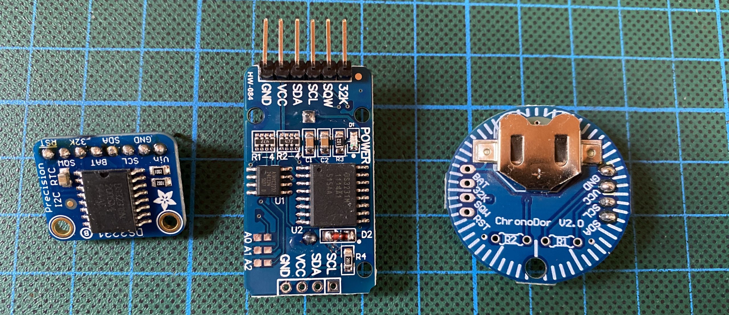 that there were a lot of breakout boards with those chips available on eBay for small money, and the specification of these chips is quite good. With only ±2 ppm for the temperature range 0° C to 40° C, they were probably the best you could buy for this kind of money. And they contain a TCXO, a temperature-compensated crystal oscillator. Unfortunately, these days, the source for the gray-market chips has dried up and now the eBay shops sell the same breakout boards with a different version, the DS3231M, which has considerably less accuracy, i.e., only ±5 ppm. Both versions contain an offset register to correct for drift caused by aging. In the picture above, you see a breakout board by Adafruit with the original chip to the left, in the middle, one of the cheap Chinese breakout boards with an M-chip (and a small EEPROM chip), and to the right is a Chronodot clone with another M-chip.
 The next two RTCs are from NXP Semiconductors. They are more energy efficient than the ones considered so far, but they use external
 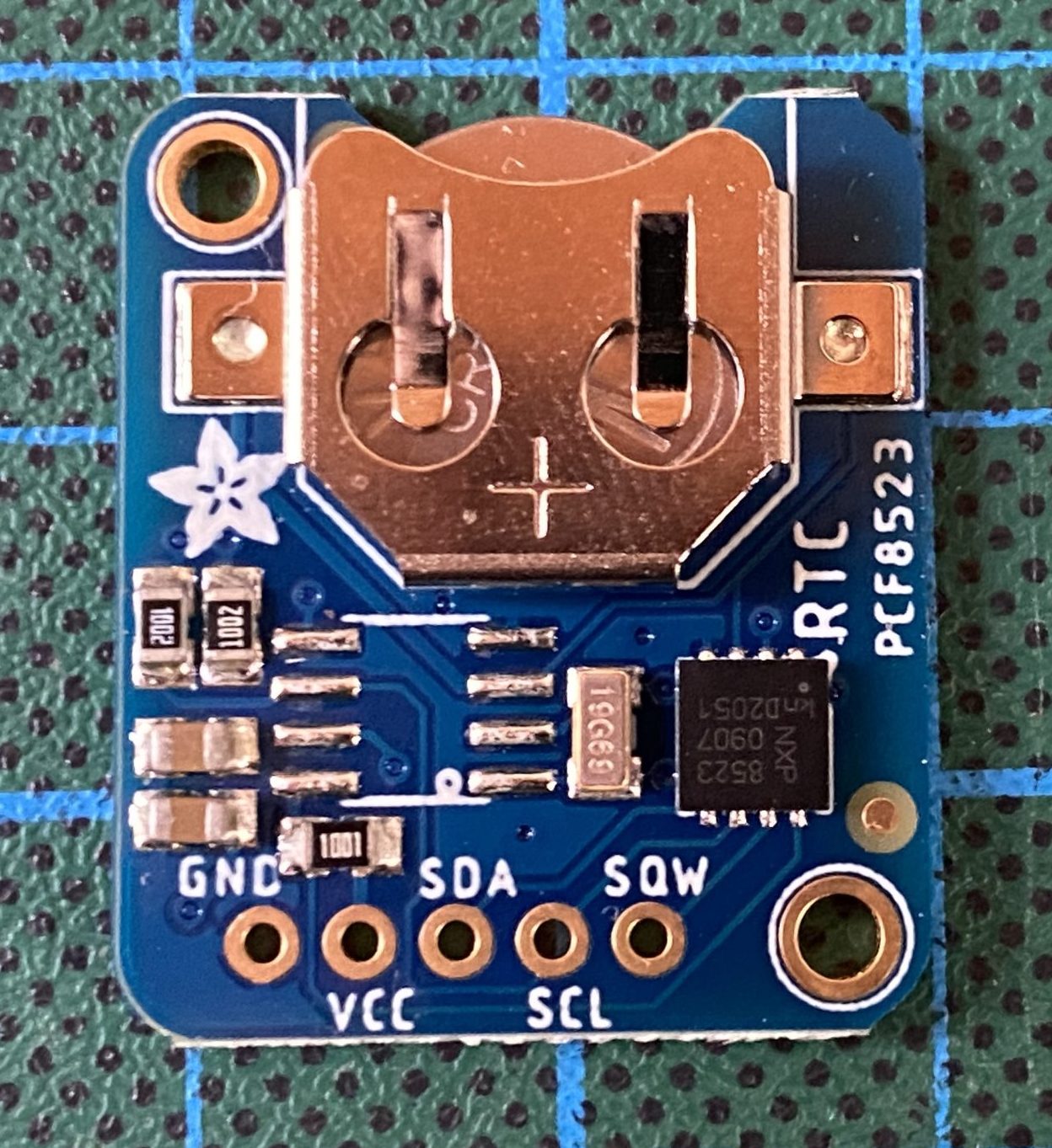 crystals. i.e., they are much less accurate than the DS3231s. It is the PCF8563 (shown in the left picture on a breakout board by Waveshare) and the PCF8523 (shown in the right picture on a breakout board by Adafruit). The latter contains an offset register that can be used to correct drift, similar to the DS3231s. If one adds a temperature sensor, one could even construct a DIY TCXO.
Now we come to RTCs that are less prominently known. The first one is  from Ricoh, a company more known for cameras and photocopiers, I believe. It is the RS5C372, which is used on a breakout board by ELV (see right picture), a German electronics company. Interestingly, it can also deal with 32 kHz crystals, and it also has an offset register to correct drift. The second one, called SD2405AL, is
 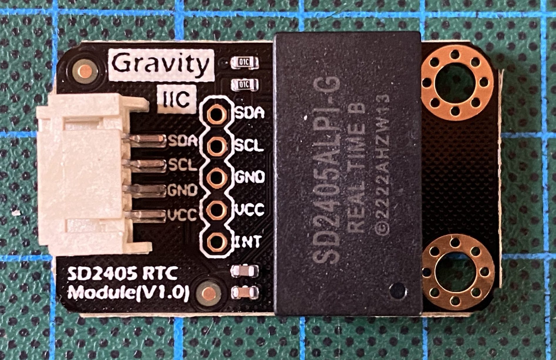 manufactured by the Chinese company WAVE. The breakout board is by DFRobot (see left picture). The interesting feature of this RTC is that it has an internal battery. Also, the crystal is integrated so that an accuracy guarantee is possible. The datasheet states ±5 ppm over the entire temperature range. However, at other points in the datasheet, it seems to be the case that the ±5 ppm applies to room temperature only. In particular, there is no mention of a TCXO.
The final three RTCs are from Micro Crystal, a Swiss company. They all are amazingly energy efficient, they can be extremely accurate, and they are unfortunately minuscule. So far, I have not tried to solder any of them to a PCB, but there are breakout boards. The first one is the 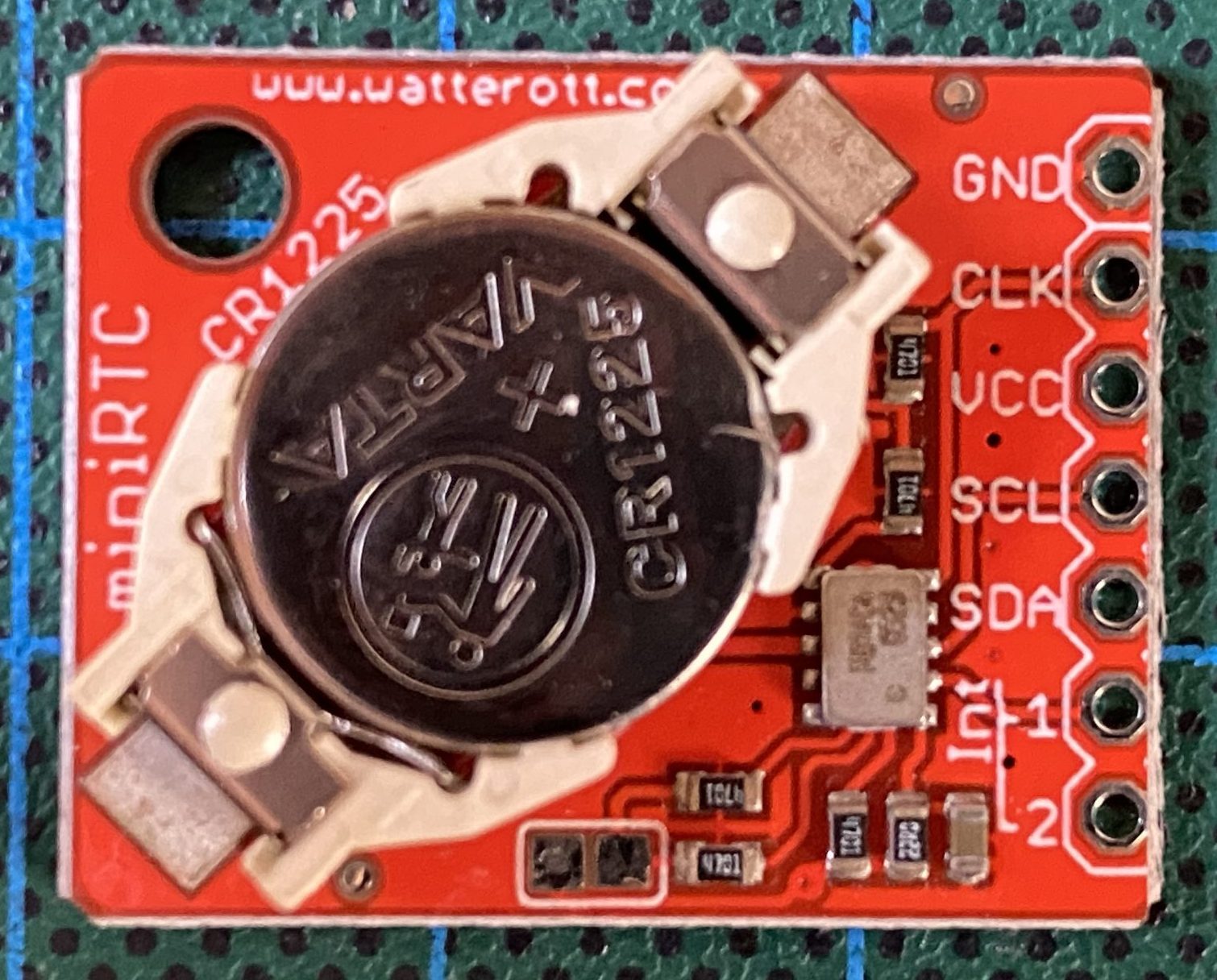 RV-8523, which sounds similar to “PCF8523”. And indeed, when you compare the register descriptions, the two RTCs look very much alike. The main difference is that the RV-8523 already contains a crystal. For this reason, one can actually provide an accuracy guarantee, which is not very tight, though. It is only ±20 ppm at room temperature.
My favorite one is the RV-8803 breakout board by Sparkfun (see right picture) , which I have used in a recent geocaching box.
  Since I was so thrilled about this RTC, I asked Micro Crystal for a free demo board (see left picture) and 5 samples of their newest creation, the RV-3032. And they indeed sent them to me. This RTC is even more accurate and more energy efficient than the RV-8803. And it is so feature rich, you probably will never be able to use all of them (such as extra RAM and EEPROM, clock output up to 67 MHz, password protection, and tamper detection). However, now there is the challenge to use these chips in one of my next projects and actually solder them to a PCB.
Finally, I added two more RTCs, which are both somehow able to ‘survive’ the next Y2K bug. Note that all the RTCs, I have talked about so far, store  only the last two digits of the year and the data sheets state that they can deal with leap years until 2099. The MCP79410 (left picture), which appears to be a successor of the MCP7940,
  has at least the leap year rule right up to 2399. And then there is the RV-3028 (right picture), which contains an unsigned 32-bit Unix timer counter. This one, if used in the Unix-style, can survive until February 7, 2016. Unfortunately, it does not offer a Unix-style alarm register. In addition to that, this RTC is the clear winner in the area of power saving.
The following table summarizes the key parameters of the RTCs I have sketched.
| ID | Manufacturer | Packages | Accuracy (± ppm) | Offset register (correction in ppm) | VBackup (V) | VActive (V) | IBackup (nA) | IStandby (µA) | Temperature (°C) | Alarm | Clock Output | Others |
|---|---|---|---|---|---|---|---|---|---|---|---|---|
| DS1307(N) | Analog Devices | DIP8 SO8 | 2.0-3.5 | 4.5-5.5 | 300 | 200.0 | 0° - +70 -40 - +85 (N version) | 0 | 1 Hz, 4.096 kHz, 8.192 kHz, 32.768 kHz | contains 56 bytes of RAM | ||
| DS1337 | Analog Devices | DIP8 SO8 µSOP8 SO16W | 1.3-1.8 | 1.8-5.5 | 425 | 1.5 | -40 - +85 | 2 | 1 Hz, 4.096 kHz, 8.192 kHz, 32.768 kHz | |||
| DS3231S(N) | Analog Devices | SO16W | 2 (0 - +40° C) 3.5 (-40 - +85° C) | -12 - +12 0.1ppm steps | 2.3-5.5 | 2.3-5.5 | 840 | 110.0 | 0 - +70 -40 - +85 (N version) | 2 | 1 Hz, 1.024 kHz, 4.096 kHz, 8.192 kHz, 32.768 kHz | uses TCXO, temperature sensor with ± 3° C |
| DS3231M | Analog Devices | SO16W SO8 | 5 | -12 - +12 0.1ppm steps | 2.3-5.5 | 2.3-5.5 | 2000 | 130.0 | -40 - +85 | 2 | 1 Hz, 1.024 kHz, 4.096 kHz, 8.192 kHz, 32.768 kHz | uses MEMS oscillator, temperature sensor with ± 3° C |
| MCP79410 | Microchip | SO8 MSOP8 TDFN8 | -127 - +127 1ppm steps | 1.3-5.5 | 1.7-5.5 | 700 | 5.0 | 40 - +85 | 2 | 1 Hz, 4.096 kHz, 8.192 kHz, 32.768 kHz | 64 bytes RAM, 128 bytes EEPROM, time-stamps for failure | |
| PCF8523 | NXP Semiconductors | SO8 TSSOP14 HVSON8 | -240 - +240 4ppm steps | 1.2-5.5 | 1.8-5.5 | 150 | 1.2 | -40 - +85 | 1 | 1 Hz, 1.024 kHz, 4.096 kHz, 8.192 kHz, 32.768 kHz | fast-mode plus I2C (1 MHz), timers | |
| PCF8563 | NXP Semiconductors | SO8 TSSOP8 HVSON10 | 1.0-5.5 | 1.8-5.5 | 250 | 0.3 | -40 - +85 | 1 | 1/16 Hz ... 32.768 kHz | contains timer | ||
| RS5C372 | RICOH | SSOP8 | -180 - +180 3ppm steps | 1.3-6.0 | 1.7-6.0 | 500 | 0.5 | -40 - +85 | 2 | 1 Hz, 32.768 kHz | can also use 32 kHz crystals, has timers | |
| RV-3028 | Micro Crystal | C7 | 1 (@25° C) | -250 - +250 0.95ppm steps | 1.1-5.5 | 1.2-5.5 | 45 | 0.1 | -40 - +85 | 1 | 1 Hz, 32 Hz, 64 Hz, 1.024 kHz, 8.192 kHz, 32.768 kHz | Unix time counter, timer, 43 byte EEPROM |
| RV-3032 | Micro Crystal | C7 | 1.5 (0 - +50° C) 2.5 (-40 - +85° C) 20 (+85 - +105° C) | -7.5 - +7.5 0.23ppm steps | 1.3-5.5 | 1.4-5.5 | 165 | 0.2 | -40 - +105 | 1 | 1 Hz ... 67.109 MHz | uses DTCXO, trickle charger for supercap, timer, time stamping, 16 byte RAM, 32 byte EEPROM |
| RV-8523 | Micro Crystal | C3 | 20 (@25° C) | -240 - +240 4ppm steps | 1.2-5.5 | 1.8-5.5 | 130 | 1.2 | -40 - +85 | 1 | 1 Hz, 32 Hz, 1.024 kHz, 4.096 kHz, 8.192 kHz, 16.384 kHz, 32.768 kHz | fast-mode plus I2C (1 MHz), timer, |
| RV-8803 | Micro Crystal | C7 | 1.5 (0 - +50° C) 3 (-40 - +85° C) 7 (+85 - +105° C) | -7.5 - +7.5 0.23ppm steps | 1.5-5.5 | 1.5-5.5 | 240 | 0.2 | -40 - +105 | 1 | 1 Hz, 1.024 kHz, 32.768 kHz | uses DTCXO, no extra battery supply, timer, time stamping |
| SD2405AL | WAVE | DIP16 | 5 | -180 - +180 3ppm steps | internal | 3.3-5.5 | 1000 | 40.0 | -40 - +85 | 1 | 1/16 Hz ... 32.768 kHz | has timers, has 12 bytes of RAM, and has an internal battery |
By the way, did I mention that there are Arduino libraries available for all of the RTCs I introduced to you? For some of them, you have to consult the web pages of the breakout board manufacturers, but most can be found by searching through the list of Arduino libraries. In particular, for the DS1307, DS3231, PCF8563, and PCF8523 (and by that the RV-8523), you can use RTClib by Adafruit, which is a fork of JeeLab’s real-time clock library.
Which RTC should one buy?
As usual, the decision of what to buy depends on your requirements and on the budget. So, let us look at how much you need to invest in the different RTCs. Below, I will list the prices for chips in single units as listed at Digi-Key and of breakout boards as you can buy them in German shops. When you order some of them directly in China, you may save another few bucks but have to wait for a couple of weeks.
| Name | Digi-Key (€) | Breakout board | Price Germany (€) | Price China (€) |
|---|---|---|---|---|
| DS1307 | 4.80 | Elecrow | 1.00 | 0.50 |
| DS1307 | 4.80 | Adafruit | 10.00 | |
| DS1337 | 4.64 | ---- | ||
| DS3231S | 14.20 | Adafruit | 17.00 | |
| DS3231M | 11.87 | No Name | 6.00 | 2.00 |
| MCP97410 | 1.30 | Mikroelektronika | 18.00 | |
| PCF8563 | 1.89 | Waveshare | 4.00 | 1.10 |
| PCF8563 | 1.89 | DIY MORE | 4.00 | 0.65 |
| PCF8523 | 1.82 | Adafruit | 10.00 | 8.00 |
| RS5C372 | 1.95 | ELV | 10.00 | |
| SD2405AL | DFRobot | 11.00 | ||
| RV-8523 | 4.64 | watterott | 10.00 | |
| RV-8803 | 4.07 | Sparkfun | 21.00 | |
| RV-3032 | 5.25 | Mikroelektronika | 15.00 | |
| RV-3028 | 3.40 | Pimorini | 15.00 | |
| RV-3028 | 3.40 | Mikroelektronika | 21.00 |
If money is the most limiting factor, the DS1307 breakout boards seems to be the right choice. Note that it has a quite high standby current and no alarm interrupt, though. If current consumption and/or an alarm interrupt are important, then the PCF8563 looks good. However, I would not buy the Waveshare board, but one with two diodes instead of a jumper. There are such boards around, which cost as much as the Waveshare board.
If you need some accuracy but have a limited budget, then the Chinese DS3231 boards are probably a good compromise. If accuracy is of utmost importance, then the RV-8803 breakout board by Sparkfun is probably best. For people who know how to solder C7 chips, the RTCs from Micro Crystal are the way to go. Their chips are much cheaper and even more accurate than the DS3231 chips.
Outlook
So what is next? I plan to set up a long-term experiment with my collection of RTCs. I already did that for a couple of DS3231 boards. However, with such a zoo of diverse RTCs, this is definitively much more challenging and interesting.
EDIT: I have added two RTCs.
EDIT: New section about battery backup.
Leave a Reply